Hemodynamics of Aortas with Multiple Overlapping Endografts: A New Design Consideration
Han Li, Kexin Lin, Anthony Palumbo, Yue Liu, Ellexis Cook and Danial Shahmirzadi
DOI10.21767/2573-4482.100049
Han Li1, Kexin Lin1, Anthony Palumbo1, Yue Liu2, Ellexis Cook1 and Danial Shahmirzadi1*
1Department of Mechanical Engineering, Stevens Institute of Technology, Hoboken, NJ 07030, USA
2Department of Biomedical Engineering, Chemistry and Biological Science, Stevens Institute of Technology, Hoboken, NJ 07030, USA
- *Corresponding Author:
- Danial Shahmirzadi
Adjunct Faculty
Department of Mechanical Engineering
Stevens Institute of Technology
Hoboken, NJ, USA
Tel: 12022860875
E-mail: dshahmir@stevens.edu
Received Date: April 29, 2017; Accepted Date: May 19, 2017; Published Date: May 26, 2017
Citation: Li H, Lin K, Palumbo A, et al. Hemodynamics of Aortas with Multiple Overlapping Endografts: A New Design Consideration. J Vasc Endovasc Surg. 2017, 2:17. doi: 10.21767/2573-4482.100049
Abstract
Endovascular Aneurysm Repair (EVAR), a method for repairing Abdominal Aortic Aneurysm (AAA), has increasingly been performed on patients with suitable anatomy, and has generated a great deal of interest toward enhancing minimallyinvasive therapeutics. However, there exist clinical cases of patients with large affected zones where one single oversized endograft does not provide a proper solution, often due to highly curved and irregular geometries. Therefore, the clinical practice of endograft implantation in patients with extended regions of arterial damage constitutes the use of multiple standard-sized endografts, usually overlapping to ensure a full coverage of the diseased areas. While being a clinically appealing practice, there exist reports on the confounding effects of using multiple, overlapping stents and the increased risk of adverse clinical outcome. The impacts of using multiple, overlapping stents on hemodynamics visa- vis cardiovascular mechanics have not been fully examined, and we speculate that resulting local flow complications contribute to the escalation of such cases. In this article, we review the arterial hemodynamic parameters in physiological conditions, as well as under employment of single and multiple stents, and highlight the major concerning impacts on the quantified flow parameters. Even though stent overlap cannot always be avoided in clinical practice, an improved stent design and overlapping deployment strategies could potentially minimize flow complications and compounding pathological effects.
Keywords
Overlapping endografts; Oversized endograft; Cardiovascular complex anatomies; Aortic hemodynamics; Device design optimization
Introduction
In 1991, the first aortic aneurysm repair using an aortic stent graft (endograft) was reported [1,2]. Endografts are devices that are secured within diseased areas of blood vessels to provide the damaged arterial walls with better structural support and to ensure functional blood flow without obstructed [3]. When first introduced, a fabric covered metallic stent would be inserted at the site of AAA without abdomen incision. In addition to bypassing an abdominal incision, aortic endografts result in considerably shorter recovery than traditional aortic aneurysm surgery. Between the years of 1991 and 1999, a boom in testing and refining of aortic endografts were undertaken on a global effort, and in 1999, the FDA approved the first human use of two endografts for the first time in the United States [4].
Though endografts are becoming more widespread, they are limited in size mostly due to manufacturing considerations and aspects relating to medical device marketing. One consequence of limited size endografts is that physicians may be unable to implant a single device in patients’ aortas restricted by the curvature and length of the blood vessels. Therefore, in patients with extended regions of damaged or diseased arteries, the common practice is to employ multiple endografts, usually 2 or 3, to cover the entire diseased area using existing commercialized endografts [5,6]. To minimize the endograft migration, an adequate grip is provided between the endografts by overlapping the endografts. Overlapping endografts also ensures coverage of the entire damaged areas.
However, stent overlap has been shown an associated increased risk of adverse clinical outcomes [7]. Several studies have investigated the biological aspects relating to stent overlap, such as hemodynamics and thrombogenicity [8-11]. There have been numerous experimental and numerical studies focusing on the hemodynamic changes in Abdominal Aortic Aneurysms (AAA) when applying a single stent [8,12-14]. Computational Fluid Dynamics (CFD) is more common for assessing the shear stress and local hemodynamics in stented arteries. More conventionally, either the peak wall stress was computed or a simulation of the interaction between blood flow and the aneurysm wall was used to determine the risk of rupture relating to the hemodynamics properties [15-17]. To determine the stress distribution in an intact AAA wall, a noninvasive methodology was developed through use of data from spiral computer tomography scans [18]. Furthermore, studies focusing on reconstructing the in situ geometry have found the wall stress to be low and uniformly distributed (e.g. peak of 120 kPa). Through statistical analysis, the AAA volume (rather than diameter) was shown to be a better indicator of high wall stress and potential of rupture. The wall stress has also been studied for aneurysms in vivo and shown to be higher at rupture than at elective repair [19]. Rupture risk was analyzed over time in patients by computation of CT data, Finite Element Analysis (FEA) in 3D computer modeling (e.g. aneurysm wall behavior), and blood pressure depicted by nonlinear hyperelastic models during observation. It was concluded that peak AAA wall stress was a better indicator of potential rupture than the AAA diameter [20]. Using a three dimensional model of a patient with AAA, the mechanical interaction between hemodynamics and wall dynamics was studied by means of a computational coupled Fluid-Structure Interaction (FSI) analysis, providing actual 3D data of the AAA geometry using CT images [21]. One challenge with these types of techniques is the lack of a clinical imaging protocol that accurately establishes the precise location and orientation of the stent struts in relation to the arterial geometry. There are approaches that have been reported in literature to avoid the limitation of simulations with idealized geometries from stent CAD data [22], including hybrid domains where CT or MRI may capture stent geometry freely on a virtually-implanted stent, [23,24] such as in vivo Micro-computed Tomography (mCT) data from explanted, stented arteries [25] and mCT images of stented artery models in vitro [26,27].
In order to examine the relatively recent and emerging clinical practice of multiple stent recruitment, the present review paper first discusses the baseline of hemodynamics (i.e., without any stent employment), in order to establish a foundation to examine hemodynamic characteristics. Then, the gradual complications in the arterial hemodynamics under recruitments of a single and multiple endografts are discussed. Finally, additional considerations for stent design and optimization are suggested that could potentially enhance the clinical outcome on patients requiring multiple stent recruitment.
Hemodynamic Characteristics without Stent Implants
Hemodynamics
Vascular diseases commonly occur at specific sites within the vascular system, such as bifurcations, stenotic necks and sacs, which are associated with abrupt disturbances to the blood flow, indicating that hemodynamics complications may play an important role in the development and progress of vascular diseases [15,16]. Accordingly, biological markers based on hemodynamics have become increasingly important in clinical diagnostic techniques [22,23]. An understanding of the arterial geometry of interest, as well as a detailed characterization of the blood-flow characteristics at the site of interest must be formed to obtain an accurate description of the vascular biomechanics under pathological development. Blood flow is characterized as a pulsatile flow, quantified by non-dimensional numbers (e.g. Reynolds) and identifying parameters, including velocity and flow waveform shapes, inter- and intra-subject variability, and frequency content. This data must be collected in order to properly examine the flow and to develop simulation device design and diagnostic models [24-28]. The ratio of inertial forces to viscous forces, the Reynolds number (Re), is used to characterize fluid flow as absolutely steady (laminar) or steady with unsteady fluctuations (turbulent). Blood flow in the human body is remarkably free of turbulence, but sounds attributed to turbulence are sometimes detected by stethoscope evaluation of the aorta [24]. The resulting turbulence increases resistance that must be balanced by a large increase in pressure to further increase the blood flow rate. Womersley number (α) varies in different human blood vessels. The equation  is used to calculate Womersley number, where r represents artery radius, v equals to the kinematic viscosity, and ω stands for the angular frequency of the oscillations [29,30]. Reynolds number for blood flow is commonly accepted to be approximately 2000 [31]; however, modeling blood flow in the human aorta indicates the formation of some turbulence in the center of the flow.
Effects on wall mechanics
Cardiovascular biomechanics is regulated highly through fluid-solid interaction mechanisms [32], and understanding the hemodynamics effects on the wall mechanics signifies the importance of the present study. One of the most common parameters in examining the vascular mechanical state, especially in regards to disease development, is the wall shear stress. Wall shear stress is the mechanical stress on the interface between flowing blood and the arterial wall during the heart cycle, depending on the dynamic viscosity and velocity gradients. Magnetic Resonance Velocimetry (MRV) has emerged as a non-invasive alternative to evaluate the condition of aorta and estimate the wall shear stress distribution using velocity measurements [18]. It is observed that two-thirds of the blood flowing through the thoracic aorta exists through the celiac trunk, the Superior Mesenteric Artery (SMA) and renal arteries during rest. By reproducing the bi-phasic flow waveform present in suprarenal aorta and the tri-phasic flow waveform found in the infrarenal aorta, the pulsatile characteristics of flow are modeled [33-36]. The magnitude of shear stress can be simulated usually by Poiseuille’s law, which states that shear stress is proportional to blood flow viscosity, and inversely proportional to the third power of the internal radius. Measurements using different modalities show that shear stress ranges between 10 and 70 dyne/cm2 in the arterial network [37]. An average aorta has a diameter of approximately 2.5 cm, which corresponds to a velocity of 48 cm/s, a mean wall shear rate of 155 s-1, and a Reynolds Number of 3400 [38]. Pressurization testing is used to assess the bulk response of the tissue to mechanical loading. Tests by Ohashi et al. on porcine thoracic aortas indicate pressurization can measure the rupture properties of human aortic aneurysms [39]. A non-invasive quantification of aortic stiffness was achieved by Georgakarakos et al., using in vivo pressurization information from blood pressure and ultrasound measurements of the maximum external diameter. The results showed the flow patterns within the different sections of the endografts, leading to characterization of pressures and stress distributions [40].
Aortas with One Stent Implant
Hemodynamic characteristics
Coronary Artery Disease (CAD) is a disease caused by atherosclerosis of the coronary arteries on the surface of the heart. In US, CAD is the primary cause of death for both men and women [41]. Approximately one-third of patients with CAD experience coronary angioplasty and stenting [24,42]. The stent allows blood perfusion to distal vessels. Implanting stents into coronary arteries can often result in damage to the arterial tissue that can re-block the vessel, and physical deformation of the artery can be caused by stent expansion [25]. Minimally invasive techniques are favorable for clinical operations because they reduce the risk associated with surgery, including operation time, recovery time, scar tissue, and infections [31]. The most common minimally invasive treatment of aortic arch aneurysms includes the use of endovascular stents [32]. One of the complications of coronary stenting is In-stent Restenosis (ISR). Endothelial Shear Stress (ESS) is a critical factor that affects the formation, progression, and heterogeneity of atherosclerotic plaques, which is determined by fluid flow velocity [40,42]. The low flow velocity results in a low ESS, and low ESS increases the possibility of synergistic pathobiological effects, enhancing injury-induced inflammation in pathobiology of Restenosis [43-45].
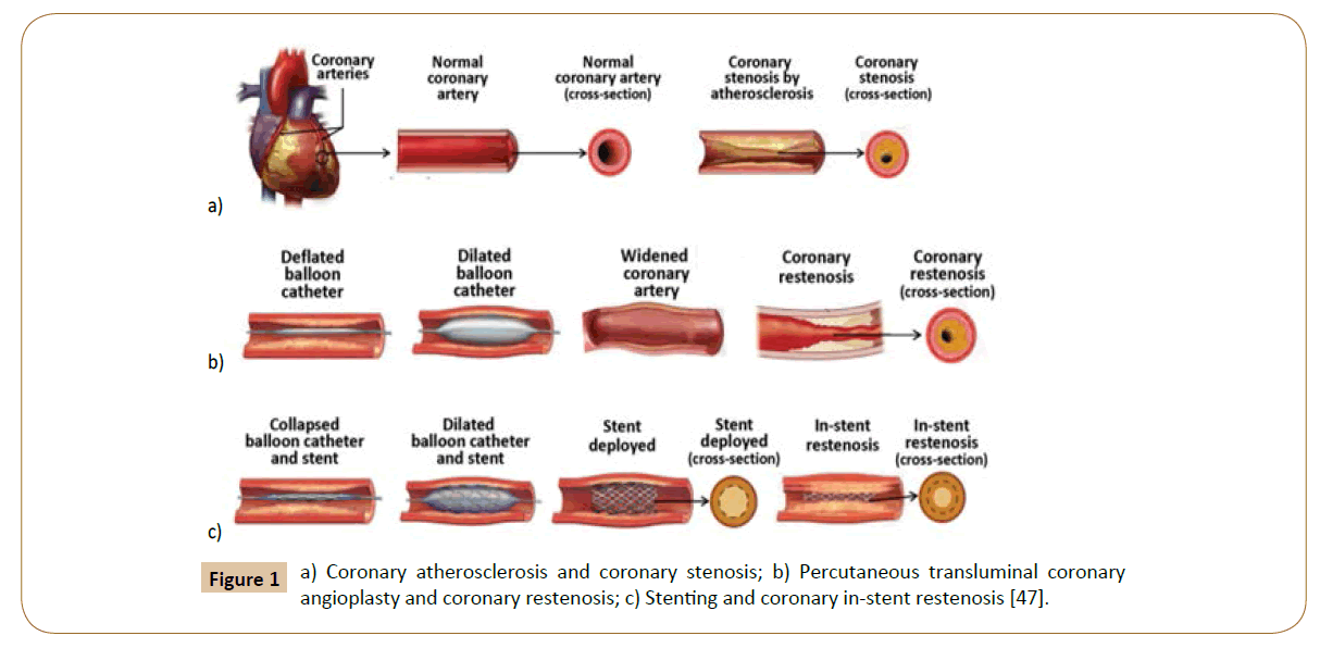
Coronary stenosis (Figure 1a) is defined as a condition where a coronary artery becomes tapered and backed up with fat and cholesterol, typically due to coronary atherosclerosis [46]. Atherosclerosis is characterized by the calcification and build-up of fatty deposits, cellular debris, and cholesterol in arteries that cause a stenotic narrowing of the vessels [47]. If this occurs in coronary arteries, the lack of oxygenated blood to the heart manifests as cardiac ischemia and angina pectoris [48]. In the case of rupture, it can trigger thrombosis, which may cause a myocardial infarction heart attack. Coronary restenosis (Figure 1b) is the reoccurrence of stenosis and is a local vascular biological response to injury. Lastly, in-stent restenosis (Figure 1c) is the narrowing of a previously stented coronary artery lumen, and is one of the biggest post-op complications for coronary stent implantation. Implantation of rigid stent frameworks alternates the 3-dimensional arterial geometry, which creates focal geometric irregularities related to strut protrusion and modifies flow velocity profiles, reducing the post-op ESS along the length of the stent, and alters the focal in-stent ESS distribution [49].
Figure 1: a) Coronary atherosclerosis and coronary stenosis; b) Percutaneous transluminal coronary angioplasty and coronary restenosis; c) Stenting and coronary in-stent restenosis [47].
Blunt injury to the thoracic vessels is the second most common cause of trauma-related death. Surgical procedures for blunt aortic injury are very challenging, but treatment has significantly improved with endovascular stent grafts. There has been an evolution of graft design and successive model improvements conforming to the actual curvature of the aortic arch [42].
Drug eluting stents
Drug-eluting stents (DES) incorporate stent technology and design with local drug delivery with the prospect of reducing restenosis and neoatherosclerotic rupture compared with bare-metal stents [50-52]. There are different compounds that can be applied on DES platforms: Cypher elutes sirolimus (SRL), and Taxus releases paclitaxel (PTX). Sirolimus (rapamycin), the first drug that was FDA approved for stents in April 2003, shown in small registry studies and randomized clinical trials to reduce the risk of restenosis in patients who were at low risk for restenosis [53]. Various studies have shown that both Sirolimus and paclitaxel efficiently prevent angiographic and clinical restenosis rates in contrast to bare metal stent [52,54,55]. However, Sirolimus-eluting and paclitaxel-eluting stents were then found to potentially be toxic and delay endothelial healing [47]. By formulating a more potent sirolimus analogue, the second-generation drug eluting stents improve the efficacy of the anti-restenotic effect expected from drug release. Zotarolimus was the first drug synthesized exclusively for treatment of in-stent restenosis. Endeavor® was then approved by the FDA in February 2008, and Endeavor® stents use a zotarolimus drug and a cobalt alloy stent with a biocompatible phosphorylcholine coating on a cobalt-chromium based driver metallic stent platform. The everolimus eluting stent was approved by the FDA in July 2008, and this stent has a different inhibitor and polymeric platform [56]. Furthermore, it is characterized by a different design that may add to their therapeutic utility and minimize a late endothelial response [47]. The existence of drug-eluting stents for treating CAD appears to offer beneficial effects in the clinical investigations; however, this comes with some limitations that need to be considered. Only a small sample size has been used in clinical trial (e.g. the largest one involved over 1000 patients, the Sirius study). In addition, CAD patients with complicating conditions, such as diabetes and bifurcated lesions were excluded from the trails. The long-term data for the efficacy and safety of this drug are lacking, and the FDA has approved the request for 5-year follow-up studies for 3 principle trails [57].
Computational fluid dynamics
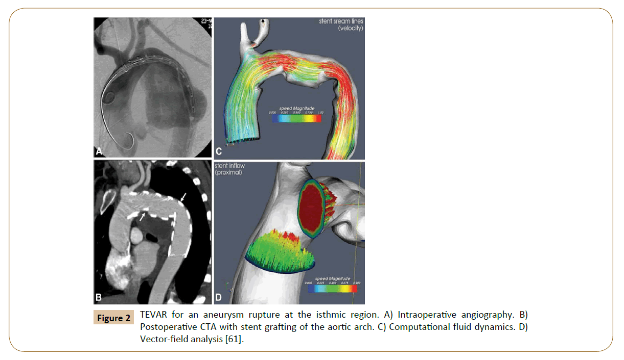
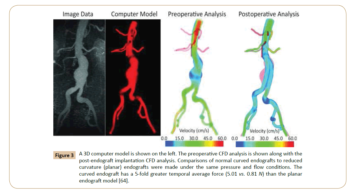
Numerical simulations of fluid flow, enabled by the CFD techniques, provide tools to quantify the hemodynamics such as the drag forces acting on the stent [58,59]. A CFD analysis was run by Lam and colleagues in 2008 to stimulate the aorta and the implanted graft to a specific patient case, in order to investigate the impact of the stent graft apposition on the displacement force acting on the stent graft [60]. CFD is also used in cardiovascular biomechanics to assess the hemodynamic condition of a vessel segment (Figure 2). Hemodynamic characteristics associated with stent implantation are difficult to quantify in vivo. CFD overcomes lack of resolution of current imaging technology and provides a realistic method of modeling arterial blood flow [61,62]. Ladisa et al. constructed a 3D computer model of an AAA and performed simulation of blood flow and pressure [63]. In the analysis, an aortic endograft was virtually implanted in the aneurysm model (Figure 3). In both the pre- and post-endograft simulations, the flow and pressure baseline conditions were kept constant.
Figure 2: TEVAR for an aneurysm rupture at the isthmic region. A) Intraoperative angiography. B) Postoperative CTA with stent grafting of the aortic arch. C) Computational fluid dynamics. D) Vector-field analysis [61].
Figure 3: A 3D computer model is shown on the left. The preoperative CFD analysis is shown along with the post-endograft implantation CFD analysis. Comparisons of normal curved endografts to reduced curvature (planar) endografts were made under the same pressure and flow conditions. The curved endograft has a 5-fold greater temporal average force (5.01 vs. 0.81 N) than the planar endograft model [64].
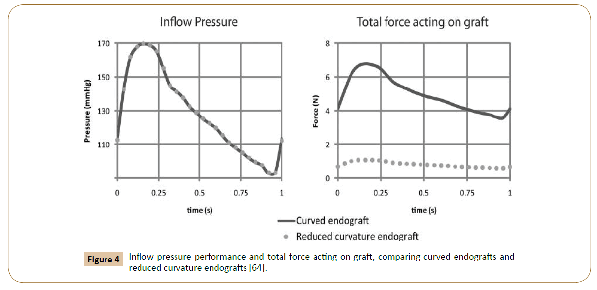
Then, the post-implantation computer model was altered to reduce endograft curvature. The flow and pressure conditions were virtually identical in comparison between the model with pulsatile forces on the normal curved endograft and the one with a modified planar endograft (Figure 4). As Figure 5 shows, the pressure field in the aorta was not influenced significantly by the changes in endograft curvature, while the marked changes in the total displacement force acting on the endograft were obtained.
Figure 4: Inflow pressure performance and total force acting on graft, comparing curved endografts and reduced curvature endografts [64].
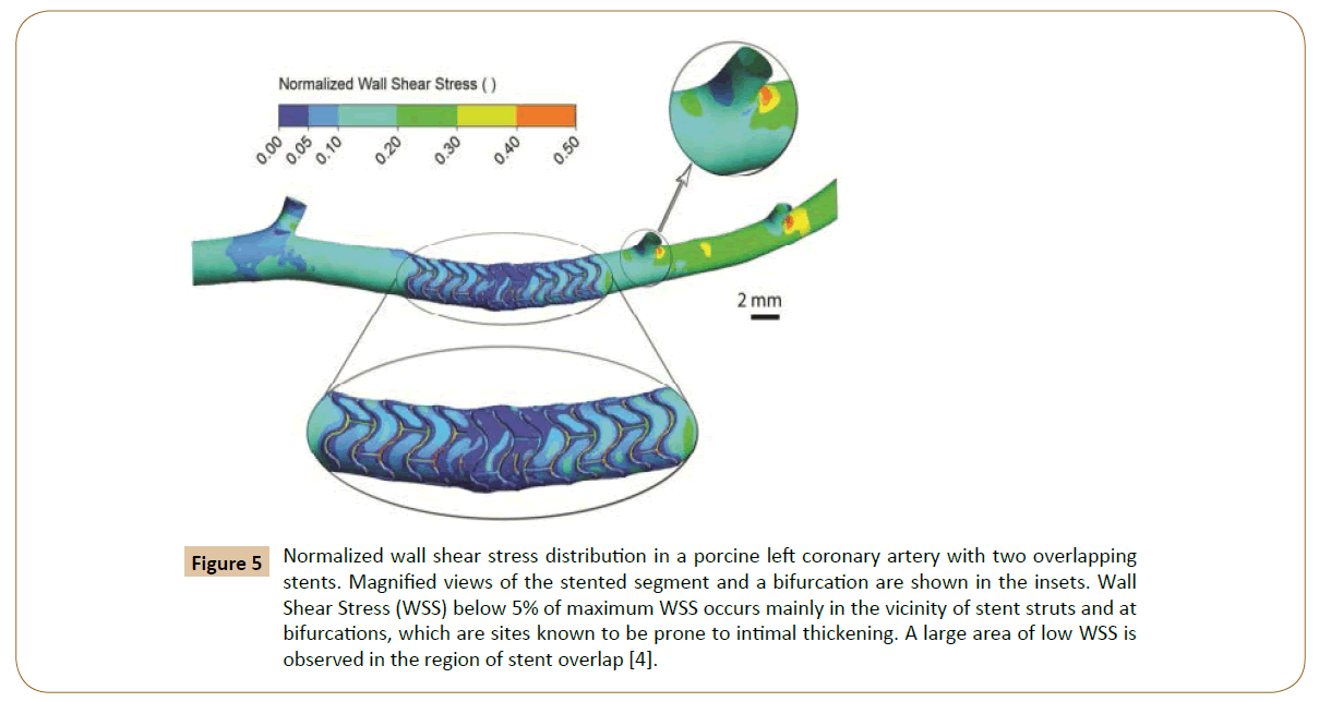
Figure 5: Normalized wall shear stress distribution in a porcine left coronary artery with two overlapping stents. Magnified views of the stented segment and a bifurcation are shown in the insets. Wall Shear Stress (WSS) below 5% of maximum WSS occurs mainly in the vicinity of stent struts and at bifurcations, which are sites known to be prone to intimal thickening. A large area of low WSS is observed in the region of stent overlap [4].
The current optimization method does not consider uncertainty in simulation or model inputs (e.g. model inflow waveform, boundary conditions, blood rheology, and stent-to-artery ratio.) that may affect the output. The total force on an endograft is presented as an estimated analysis. In reality, actual endograft migration will also depend on a number of other factors, such as the friction between the wall and graft, fixed length, longitudinal columnar force, and the influence of penetrating hooks and barbs that are not considered in this analysis. Computational methods are valuable in isolating and understanding mechanisms, but idealized models do not account for all possible clinical considerations and complexities.
Hemodynamic Characteristics in Aortas with Overlapping Stent Implants
Stent overlap was defined as the presence of at least two separate stents within a single treated lesion and an overlapping stent zone of at least 1 mm [7]. Adverse events, such as increased in-stent restenosis and lumen loss, are associated with stent overlap due to increased inflammation and delayed healing regardless of stent type [10,64,65]. Stent malapposition has been shown to increase thrombogenicity [10]. It is hypothesized that hemodynamics plays a role therein, as the contents between high shear stress area and recirculation zone caused by malapposed stents result in active platelets and improve the local residence time of the thrombocytes [10,35,65]. Kolandaivelu et al. have shown both in vivo and via computational model with idealized domain geometry that the stent thrombogenicity could possibly be modulated by the flow recirculation between overlapping and malapposed stent struts [66].
Common quantification techniques
Computational Fluid Dynamics (CFD) has been one of the significant tools in assessing mechanical properties such as shear stress and local hemodynamics in stented arteries [67]. The accurate acquisition of the stent struts and arterial geometry is fundamental for precise CFD analysis, but lack of clinical imaging modalities that could yield such data with sufficient resolution has been a challenge [68]. Several approaches have been reported in the literature to circumvent this limitation; for instance, conducting simulations on idealized geometries based on stent CAD data [69,70], on hybrid domains where the stent geometry is freely obtained by CT, or MRI as a contribution of a virtually-implanted stent [57,70], on ex vivo Micro-computed Tomography (mCT) data of explanted, stented arteries [21] or mCT images of stented in vitro artery models [22,63]. Although these approaches have their particular advantages, they result in either inaccurate geometric data, narrow treatable domain size in aorta, and/or under-defined expression of the mechanical interaction between the stent and aorta wall.
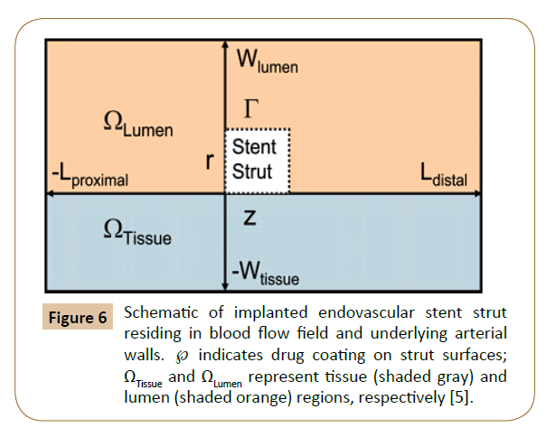
Balakrishnan et al. have created a mathematical model based on the drug eluting stent, which the computational domain comprised an idealized section as a rectangle in long axial arteries without relative to strut dimensions (Figure 6). The results showed that local drug load and blood flow were higher than normal, and the direct contact between tissue and strut were increased by the influence of overlapping stents. The relative strut shape and configuration effected the final drug deposition. Correspondingly, no large difference was found between the flow fields with stacked and side-by-side configurations versus those of single struts with twice the width or height. Mathematical modeling is essential when clinical and animal studies indicate areas of concern without fully identifying them.
Figure 6: Schematic of implanted endovascular stent strut residing in blood flow field and underlying arterial walls. ℘ indicates drug coating on strut surfaces; ΩTissue and ΩLumen represent tissue (shaded gray) and lumen (shaded orange) regions, respectively [5].
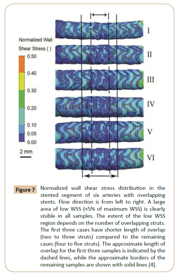
Rikhtegar et al. worked on the hemodynamics in coronary arteries with overlapping stents [68]. The results showed that the relative size of low wall shear stress areas is increased significantly in regions of stent overlap compared to non-overlapped regions (Figure 5). Normalized wall shear stress also distributes differently in various overlapping stents (Figure 7). Since low wall shear stress is generally accepted as a factor in atherogenesis and thrombogenesis, they conclude that the adverse hemodynamics caused by stent overlap may be responsible in part for the adverse clinical outcome in patients that are treated with overlapping stents.
Figure 7: Normalized wall shear stress distribution in the stented segment of six arteries with overlapping stents. Flow direction is from left to right. A large area of low WSS (<5% of maximum WSS) is clearly visible in all samples. The extent of the low WSS region depends on the number of overlapping struts. The first three cases have shorter length of overlap (two to three struts) compared to the remaining cases (four to five struts). The approximate length of overlap for the first three samples is indicated by the dashed lines, while the approximate borders of the remaining samples are shown with solid lines [4].
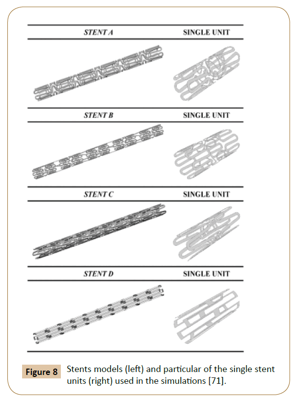
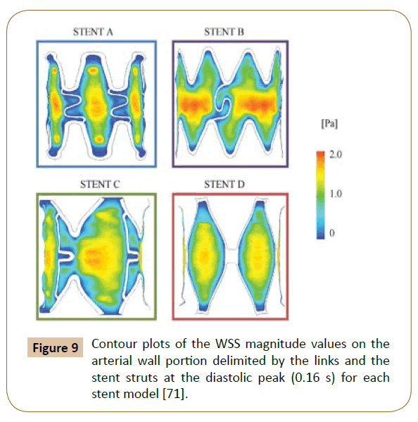
A 3D model with 4 different structures (Figure 8) of stents was built by Balossino et al. to run this coronary stent and disruption of an atheromatous plaque simulation in ANSYS. The results (Figure 9) reported the Wall Shear Stress (WSS) spatial distribution on the ‘vessel area’ within the stent, which is quite similar for all models: The values increase from the zones near the stent struts towards the center of the vessel region [71]. The observations also agreed with the results reported by Ladisa et al. [72].
Figure 8: Stents models (left) and particular of the single stent units (right) used in the simulations [71].
Figure 9: Contour plots of the WSS magnitude values on the arterial wall portion delimited by the links and the stent struts at the diastolic peak (0.16 s) for each stent model [71].
Discussion and Conclusion
Choosing proper boundary conditions significantly contributes to the correct calculation of WSS distribution, and in- and out-flow conditions of subject-specific measurements would give more precise results. As different imaging modalities, such as invasive intravascular Doppler ultrasound, phase contrast magnetic resonance imaging or in vivo flow could be utilized. Stenting was released partially to allow blood flow and mitigate artery diseases. The biological response of the vascular wall is not considered here. Incorporating more complex models that take into account vascular biology and transport processes would give deeper insight into the topic, as would the inclusion of a wall injury model. The latter is relevant due to the increased mechanical load in areas of stent overlap. Hemodynamics also influences the distribution and uptake of drugs eluted from DES, and the effect of flow on local drug concentration should be characterized more thoroughly. Given the significance of the altered hemodynamics on proper cardiovascular mechanics and functioning when undergoing multiple-stent employment, future work needs to be conducted on developing appropriate constitutive models for the different tissues, in order to explicitly represent their interactions. CSM analysis considered only the temporal mean of the displacement force uniformly distributed through the surface of the endograft. In reality, the displacement forces vary spatially and temporally, and these variations may play an important role in the evolution of contact stresses at the endograft junctions [32]. The measurements of flow and pressure are essential for further clarification between inflow and outflow boundary conditions in static or higher flow extension condition [33]. 3D printing customized vascular stent is viewed as another promising trend in future work. Metal is widely used as a reliable material for stents to ensure strength [73]. However, according to recent research by Ameer and Cheng from Northwestern University, citric-acid based polymer is used as a new 3D printing material of stent, which provides flexible, biodegradable and inherent antioxidant properties. Compared with metal, citric-acid is safer to the body. Meanwhile, advancements in 3D printing technology could help physician and patient to build unique best-fit vascular stents, instead of using existing stent with different sizes [74]. With the combination method of both mathematical and animal-based modeling, the direct contact of struts with particular tissue is shown to be important but not indispensable due to the uncertain linearly scaling of drug deposition with either drug load or stent-artery contact area. Tissue concentration essentially depends on the relative positioning of struts and flow over the stent. More innovative and efficient approaches on drug delivering to vascular patients may be created by more studies with computational models, as the process of identifying the kinetics of drug releasing and tissue uptake. Based on the result of the study conducted by Rikhtegar et al. [68], in cases where stent overlap cannot be avoided, new deployment strategies or stent designs should be considered to reduce the size of low wall shear stress areas. Although customized vascular stent has not been a prevalent clinical practice, enhanced precision, reliability and affordability of such products could promote practice of employing personalized endografts [75,76].
References
- Parodi JC, Palmaz JC, Barone HD (1991) Transfemoral intraluminal graft implantation for abdominal aortic aneurysms. Ann Vasc Surg 5: 491-499.
- Greenhalgh RM, Powell JT (2008) Endovascular repair of abdominal aortic aneurysm. N Engl J Med 358: 494-501.
- Conrad MF, Adams AB, Guest JM (1991) Secondary intervention after endovascular abdominal aortic aneurysm repair. Ann Surg 250: 383-389.
- Fogarty TJ, Arko FR, Zarins CK (2004) Endograft technology: highlights of the past 10 years. J Endovasc Ther 192-199.
- Byrne RA, Joner M, Kastrati A (2015) Stent thrombosis and restenosis: what have we learned and where are we going? The Andreas Gru¨ntzig Lecture ESC 2014. Europ Heart J 3320-3331.
- Buxton B (2008) The role of stents in the current era: long-term antiplatelet therapy and late-stent thrombosis. ANZ J Surg 78: 2-5.
- Raber L, Juni P, Loffel L, Wandel S (2010) Impact of stent overlap on angiographic and long-term clinical outcome in patients undergoing drug-eluting stent implantation. JAC 55: 1178-1188.
- Repository ZO (2014) Hemodynamics in coronary arteries with overlapping stents Hemodynamics in coronary arteries with overlapping stents 47: 505-511.
- Luscher TF, Steffel J, Eberli FR, Joner M, Nakazawa G, et al. (2007) Drug-eluting stent and coronary thrombosis biological mechanisms and clinical implications. Circulation 1051-1058.
- Kolandaivelu K, Swaminathan R, Gibson WJ, Kolachalama VB, Giddings VL, et al. (2011) Stent thrombogenicity early in high-risk interventional settings is driven by stent design and deployment and protected by polymer-drug coatings. Circulation 1400-1409.
- Attizzani GF, Capodanno D, Ohno Y (2014) Mechanisms, pathophysiology, and clinical aspects of incomplete stent apposition.
- Suh GY, Les AS, Tenforde AS, Shadden SC, Spilker RL, et al. (2011) Hemodynamic changes quantified in abdominal aortic aneurysms with increasing exercise intensity using MR exercise imaging and image-based computational fluid dynamics. Ann Biomed Eng 39: 2186-2202.
- Efstratios G, George SG, Konstantinos CK, Evagelos N, Miltos L, et al. (2012) Studying the flow dynamics within endografts in abdominal aortic aneurysms. INTECH 8: 151-168.
- Salsac AV (2005) Changes in the hemodynamic stresses occurring during the enlargement of abdominal aortic aneurysms pp: 1-156.
- Nghiem TP, Moreno R, Tran MH, Salvayre AN, Rousseau H, et al. (2014) Computational fluid dynamics: morphological and hemodynamic changes in abdominal aortic aneurysm. JACC 63: A1213.
- Frauenfelder T, Lotfey M, Boehm T (2006) Computational fluid dynamics: hemodynamic changes in abdominal aortic aneurysm after stent-graft implantation. Cardiovasc Intervent Radiol 29: 613.
- Ladisa JF, Olson LE, Guler I, Hettrick DA, Audi SH, et al. (2004) Stent design properties and deployment ratio influence indexes of wall shear stress: a three-dimensional computational fluid dynamics investigation within a normal artery. J App Physiol 97: 424-430.
- Fillinger MF, Marra SP, Raghavan ML, Kennedy FE (2003) Prediction of rupture risk in abdominal aortic aneurysm during observation: wall stress versus diameter. J Vasc Surg 37: 724-732.
- Di Martino ES, Guadagni G, Fumero A, Ballerini G, Spirito R, et al. (2001) Fluid-structure interaction within realistic three-dimensional models of the aneurysmatic aorta as a guidance to assess the risk of rupture of the aneurysm. Med Eng Phys 23: 647-655.
- Gundert T, Shadden S, Williams A, Koo BK, Feinstein J, et al. (2011) A rapid and computationally inexpensive method to virtually implant current and next-generation stents into subject-specific computational fluid dynamics models. Ann Biomed Eng 39: 1423-1437.
- De Santis G, Mortier P, De Beule M, Segers P, Verdonck P, et al. (2010) Patient-specific computational fluid dynamics: structured mesh generation from coronary angiography. Med Biol Eng Comput 48: 371-380.
- Morlacchi S, Keller B, Arcangeli P, Balzan M, Migliavacca F, et al. (2011) Hemodynamics and in- stent restenosis: micro-CT images, histology, and computer simulations. Ann Biomed Eng 39: 2615-2626.
- Claudio C, Stefano M, Simon P, Gabriele D (2012) Computational fluid dynamics: hemodynamic changes in abdominal aortic aneurysm after stent-graft implantation. Eur J Mech B Fluids 35: 76-84.
- Holdsworth DW, Rickey DW, Drangova M, Miller DJM, Fenster A (1991) Computer-controlled positive displacement pump for physiological flow simulation. Med Biol Eng Comput 29: 565-570.
- Frayne R, Holdsworth DW, Gowman LM, Rickey DW, Drangova M, et al. (1992) Computer controlled flow simulator for MR flow studies. J Magn Reson Imaging 2: 605-612.
- Wang ZJ, James MB, Michael HD (2003) Unsteady forces and flows in low Reynolds number hovering flight two-dimensional computations vs. robotic wing experiments. J Experi Biol 207: 449-460.
- Rohlf K, Tenti G (2001) The role of the Womersley number in pulsatile blood flow. J Biomech 34: 141-148.
- Ponzini R, Vergara C, Rizzo G (2010) Womersley number-based estimates of blood flow rate in Doppler analysis: in vivo validation by means of phase-contrast MRI. IEEE Transactions on Biomedical Engineering 57: 1807-1815.
- Moloy KB, Ranjan G, Amitava D (2012) Effect of pulsatile flow waveform and womersley number on the flow in stenosed arterial geometry. ISRN Biomathematics.
- Li John KJ (1996) Comparative cardiovascular dynamics of mammals.
- Ghalichi F, Deng X, De CA, Douville Y, King M, et al. (1998) Low Reynolds number turbulence modeling of blood flow in arterial stenoses. Biorheology 35: 281-294.
- Danial S, Elisa EK (2014) Quantification of arterial wall inhomogeneity size, distribution, and modulus contrast using FSI numerical pulse wave propagation. Artery Res 8: 57-65.
- Christopher JE, Marcus TA (2007) Magnetic resonance velocimetry: applications of magnetic resonance imaging in the measurement of fluid motion. Exp Fluids 43: 823.
- Moore JE, Ku DN (1994) Pulsatile velocity measurements in a model of the human abdominal aorta under resting conditions. J Biomech Eng 116: 337-346.
- Wang K, Zhou XR, Verbeken E, Ping QB, Huang YM, et al. (2000) Overlapping coronary stents result in an increased neointimal hyperplasia: insight from a porcine coronary stent model. J Interv Cardiol 13: 173-177.
- Chatzizisis YS, Coskun AU, Jonas M, Edelman ER, Feldman CL, et al. (2007) Role of endothelial shear stress in the natural history of coronary atherosclerosis and vascular remodeling: molecular, cellular, and vascular behavior. J Am Coll Cardiol 49: 2379-2393.
- Malek AD, Alper SL, Izumo S (1999) Hemodyanmic shear stress and its role in atherosclerosis. JAMA 282: 2035-2042.
- Matthew AA, Kevin K (2008) The epidemiology of abdominal aortic diameter. J Vas Sur 48: 121-127.
- Toshiro O, Syukei S, Takeo M, Kiichiro K, Hiroji A, et al. (2003) Rupture properties of blood vessel walls measured by pressure-imposed test. JSME 46: 1290-1296.
- Koskinas KC, Chatzizisis YS, Antoniadis AP, Giannoglou GD (2012) Role of endothelial shear stress in stent restenosis and thrombosis pathophysiologic mechanisms and implications for clinical translation. JAC 59: 1337-1349.
- Xu J, Sheery LM, Kenneth DK, Brigham AB (2016) Deaths: Final data for 2013. National Vital Statistics Reports 64.
- O’Connor JV, Byrne C, Thomas MS, Bartley PG, Neschis DG (2009) Vascular injuries after blunt chest trauma: diagnosis and management. J Ame Coll Cardiol 59: 1337-1349.
- Papafaklis MI, Bourantas CV, Theodorakis PE (2009) Relationship of shear stress with in-stent restenosis: bare metal stenting and the effect of brachytherapy. Int J Cardiol 134: 25-32.
- Sanmartin M, Goicolea J, Garcia C (2006) Influence of shear stress on in-stent restenosis: in vivo study using 3D reconstruction and computational fluid dynamics. Rev Esp Cardiol 59: 20-27.
- Thury A, Wentzel JJ, Vinke RV (2002) Focal in-stent restenosis near step-up: roles of low and oscillating shear stress. Circulation 105: 185-187.
- Qiao A, Liu Y (2007) Hemodynamics simulation of aortic arch aneurysm with partly bridged endovascular stent international federation for medical and biological engineering.
- O’Connor JV (2009) Vascular injuries after blunt chest trauma: diagnosis and management Scandinavian. J Trauma Resusci Emer Med 17: 42.
- O’Connell BM, Mcgloughlin TM, Walsh MT (2010) Factors that affect mass transport from drug eluting stents into the artery wall. BioMed Eng Online pp: 6-8.
- Morris DC (1977) Hemodynamic results of aortic valvular replacement with the porcine xenograft valve. Circulation 56: 841-844.
- Yin R, Yang D, Wu J (2014) Nanoparticle drug and gene eluting stents for the prevention and treatment of coronary restenosis. Theranostics 4: 175-200.
- Garcia-Garcia HM, Vaina S, Tsuchida K, Serruys PW (2006) Drug-eluting stents. Arch Cardiol Mex 76: 297-319.
- van’t Veer M, Pijls NH, Aarnoudse W, Koolen JJ, van de Vosse FN, et al. (2006) Evaluation of the haemodynamic characteristics of drug-eluting stents at implantation and at follow-up. Euro Heart J 27: 1811-1817.
- Moses JW, Leon MB, Popma JJ, Fitzgerald PJ, Holmes DR, et al. (2003) Sirolimus-eluting stents versus standard stents in patients with stenosis in a native coronary artery. N Engl J Med 349: 1315-1323.
- Kastrati A, Dibra A, Eberle S (2005) Sirolimus-eluting stents vs. paclitaxel-eluting stents in patients with coronary artery disease: meta-analysis of randomized trials. JAMA 294: 819-825.
- Babapulle MN, Joseph L, Belisle P, Brophy JM, Eisenberg MJ (2004) A hierarchical Bayesian meta-analysis of randomised clinical trials of drug-eluting stents. Lancet 364: 583–591.
- Patrick W, Serruys (2010) Comparison of Zotarolimus-Eluting and Everolimus-Eluting Coronary Stents. N Engl J Med 363: 136-146.
- Leon MB, Moses JW (2003) review of drug-eluting stents: why all the excitement? Adv Stud Med 3: S592-601.
- Kim M, Taulbee DB, Tremmel M, Meng H (2008) Comparison of two stents in modifying cerebral aneurysm hemodynamics. Ann Biomed Eng 365: 726-741.
- Seshadhri S, Janiga G, Thevenin D (2011) Impact of stents and flow diverters on hemodynamics in idealized aneurysm models. J Biomech Eng 133: 071005.
- Cheng SWK, Lam ESK, Fung GSK (2008) A computational fluid dynamic study of stent graft remodeling after endovascular repair of thoracic aortic dissections. J Vasc Surg 48: 303-310.
- Midulla M, Moreno R, Baali A, Chau M, Negre-Salvayre A, et al. (2012) Haemodynamic imaging of thoracic stent-grafts by computational fluid dynamics (CFD): presentation of a patient-specific method combining magnetic resonance imaging and numerical simulations. Eur Radiol 22: 2094-2102.
- Gundert TJ (2009) Improving cardiovascular stent design using patient-specific models and shape optimization.
- Ladisa JF, Olson LE, Douglas HA, Warltier DC, Kersten JR, et al. (2006) Alterations in regional vascular geometry produced by theoretical stent implantation influence distributions of wall shear stress: analysis of a curved coronary artery using 3D computational fluid dynamics modeling. Biomed Eng Online 5: 40.
- Figueroa CA, Taylor CA, Yeh V, Chiou AJ, Zarins CK (2009) Effect of curvature on displacement forces acting on aortic endografts: a 3-dimensional computational analysis. J Endovasc Ther 16: 284-294.
- Hathcock JJ (2006) Flow effects on coagulation and thrombosis. Arterioscler Thromb Vasc Biol 26: 1729-1737.
- Peacock J, Hankins S, Jones T, Lutz R (1995) Flow instabilities induced by coronary artery stents: assessment with an in vitro pulse duplicator. J Biomech 28: 17-26.
- Beier S, Ormiston J, Webster M, Cater J, Norris S, et al. (2016) Hemodynamics in idealized stented coronary arteries: important stent design considerations. Ann Biomed Eng 44: 315-329.
- Rikhtegar F, Pacheco F, Wyss C, Stok KS, Ge H, et al. (2013) Compound ex vivo and in silico method for hemodynamic analysis of stented arteries. PloS ONE 8: e58147.
- Benndorf G, Ionescu M, Alvarado MV, Hipp J, Metcalfe R (2009) Wall shear stress in intracranial self-expanding stents studied using ultra-high- resolution 3D reconstructions. Am J Neuroradiol 30: 479-486.
- Connolley T, Nash D, Buffière JY, Sharif F, McHugh PE (2007) X-ray micro-tomography of a coronary stent deployed in a model artery. Med Eng Phys 29: 1132-1141.
- Balossino R, Gervaso F, Migliavacca F, Dubini G (2008) Effects of different stent designs on local hemodynamics in stented arteries. J Biomech 41: 1053-1061.
- LaDisa JF, Guler I, Olson LE, Hettrick DA, Kersten JR, et al. (2003) Three-dimensional computational fluid dynamics modeling of alterations in coronary wall shear stress produced by stent implantation. Ann Biomed Eng 31: 972-980.
- Walkea W, Paszendaa Z (2005) Experimental and numerical biomechanical analysis of vascular stent. J Mat Proc Tech 699-702.
- Morris A (2016) 3-D printing customized vascular stents.
- Xu J, Yang J, Sohrabi S, Zhou Y, Liu Y (2017) Finite element analysis of the implantation process of overlapping stents. ASME J Med Devices 11: 021010.
- Mori H, Lutter C, Yahagi K, Harari E, Kutys R, et al. (2017) Pathology of chronic total occlusion in bare-metal versus drug-eluting stents: implications for revascularization. JACC 10: 367-378.
Open Access Journals
- Aquaculture & Veterinary Science
- Chemistry & Chemical Sciences
- Clinical Sciences
- Engineering
- General Science
- Genetics & Molecular Biology
- Health Care & Nursing
- Immunology & Microbiology
- Materials Science
- Mathematics & Physics
- Medical Sciences
- Neurology & Psychiatry
- Oncology & Cancer Science
- Pharmaceutical Sciences
